Print
Discovery Telecom
Advanced Interception Systems.
Intelligence and surveillance
Tel./Fax: +353 1 902 6688
E-mail: info@intercept.ws

Tactical Thuraya Satellite Interceptor (TIS)

Tactical Thuraya Interceptor

Main characteristics
 
Vendor Intercept
Category Satellite interception
Standart Thuraya/L-band
Frequency L Band (950–1750 MHz)
System output Voice, SMS and call related data
Power source 115/230V AC, or 12/24V DC, 300W
Active range (m) 600000
OS Windows
Decryption Built In
Battery Optional
Display 17” TFT, 1366 x 768
SMS(MMS) in all languages
Antenna Single, Active, Omni Directional
Q'ty of channels 48
Protocols IMEI, TMSI, IMSI
Analogue Fax support Yes
Management API, IP
Dimensions, HWD 331 x 82 x 268 mm
Weight 7 kg
Shipment According to EUC

The main functions and characteristics

One platform for Thuraya and Iridium 
new_icon.jpg 

You can make Iridium from Thuraya system and vice versa by purchasing an additional license.

Intercept of Up Channel - up to 15 km, Down Channel - up to 2000 km

TIS can monitor the following Thuraya services:

red1.jpg Voice, SMS, fax and data;
red1.jpg Interception of up to 8 spot-beams simultaneously monitored;
red1.jpg Interception of up to 48 duplex calls simultaneously;
red1.jpg Decryption unit built in.

TIS is designed to be easily transported to the places of operations. Quickly deployable and operational in a couple of minutes. The system is suitable for use in land, sea and air applications.

TIS is a rapidly deployable system for monitoring communications on the Thuraya satellite mobile communications systems. Call interception is passive, and thus not detectable by either the mobile user or the satellite network.

Control of the system is via an intuitive windows-based GUI. Incoming calls are displayed in real-time, and voice is played via laptop unit. Software to decode and display a number of fax and data protocols is included. Information relating to the identification of called and calling parties is recorder.

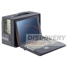
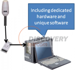
The system consists of the receiver, the control unit (laptop) and an antenna set.

Key features:

red1.jpg Mobile satellite monitoring in radio line of sight
red1.jpg Map functionality (own position, target position and beam position)
red1.jpg Small, portable form factor
red1.jpg Light weight
red1.jpg L-band „target“ and „satellite“ inputs
red1.jpg DC powered via AC adapter or vehicle adapter

Antennas:

TIS is supplied with antennas and cables for quick and easy deployment. One antenna is required to capture the satellite downlink, while the second (target) antenna captures the signal by the mobile terminal. Optional a range of antennas for a variety of deployment scenarios can be supplied by our company, including vehicle mounted and omni-directional antennas. The system also features variable attenuation to allow effective operation under a wide range of signal conditions typically experienced in the tactical environment.

Main services of the Thuraya Satellite Interceptor 

• Voice communication;
• Dial‐up data transmission;
• GmPRS batch communication;
• Facsimile communication;
• Transmission of short messages;
• Defining of geographical position of subscribers. 

 
TIS provides

• Interception of voice communication;

• Interception of Facsimile communications;
• Interception of short text messages;
• Interception of data transmitted between terminals of the system;
• Interception of call related information;
• Defining of geographical position of Thuraya terminals;
• Continued (24/7) operation, processing and storage of information;
• Full‐range and flexible retrieval of stored information on the user demand;
• Issuing of reports and recommendations based on stored information assessments. 


System structure  

The system consists of a receiver, a control unit (laptop) and an antenna kit.

The receiver is designed to receive and amplify the signal, and the computing part is for processing and storing intercepted data


Detailed Components List

                     
a. TIS‐RF‐L  The subsystem receives and amplifies high‐frequency signal which comes from a L‐band satellite antenna and rely it to processing subsystem TIS‐P.  
b. TIS‐RF‐L‐M  The system is similar to the TIS‐RF‐L but used for configuration with multiple L‐band antennas and works in conjunction with TIS‐P‐M subsystem.  
c. TIS‐P  The subsystem is for processing of communication signals relied from TIS‐RF‐L and TIS‐RF‐L‐M subsystems. It identifies communication sessions and carries out other necessary functions related to data processing, as well as storage and processing of accumulated data.  
d. TIS‐P‐M  The subsystem is for processing of communication signals relied from TIS‐RF‐L‐M subsystem. For full operation of entire system a communication link with TIS‐P subsystem will be required
.

*Detailed documentation is available only to registered partners with STS status